I2C (Inter-integrated Circuit)
Introduction
In this tutorial, you will learn all about the I2C communication protocol, why you would want to use it, and how it’s implemented on microcontroller. I2C is a serial protocol for two-wire interface to connect low-speed devices like microcontrollers, EEPROMs, A/D and D/A converters, I/O interfaces and other similar peripherals in embedded systems.

Serial, 8-bit, bidirectional data transfer can occur at speeds up to 3.4Mbps, though 400kHz is usually sufficient. Since only two bus lines are required, a
serial data line (SDA) and serial clock line (SCL), building a system with multiple master or slave devices is relatively simple. The number of I2C devices
that can be connected to a single I2C bus segment is limited only by a maximum bus capacitance (400pF) and address space.
Why Use I2C?
 |
| I2C Block Diagram |
I2C requires a two wires, like asynchronous serial communication, but those two wires can support up to 1008 slave devices. Also, unlike SPI, I2C can support a multi-master system, allowing more than one master to communicate with all devices on the bus (although the master devices can’t talk to each other over the bus and must take turns using the bus lines).
Data rates fall between asynchronous serial and SPI, most I2C devices can communicate at 100kHz or 400kHz. There is some overhead with I2C, for every 8 bits of data to be sent, one extra bit of data (the “ACK/NACK” bit, which we’ll discuss later) must be transmitted.The hardware required to implement I2C is more complex than SPI, but less than asynchronous serial(RS232). It can be also implemented in software.
I2C bus is popular because it is simple to use, there can be more than one master, I2C can use even slower microcontrollers with general-purpose I/O pins since they only need to generate correct Start and Stop conditions in addition to functions for reading and writing a byte.
I2C - A Brief History
I2C was originally developed in 1982 by Philips for various Philips chips. The original spec allowed for only 100kHz communications, and provided only for 7-bit addresses, limiting the number of devices on the bus to 112 (there are several reserved addresses, which will never be used for valid I2C addresses). In 1992, the first public specification was published, adding a 400kHz fast-mode as well as an expanded 10-bit address space.
There are three additional modes specified:
- fast-mode at 1MHz.
- high-speed mode at 3.4MHz.
- ultra-fast mode at 5MHz.
I2C at the Hardware Level
Each I2C bus consists of two signals: SCL and SDA.
- SCL is the clock signal
- SDA is the data signal.
The clock signal is always generated by the current bus master, some slave devices may force the clock low at times to delay the master sending more data (or to require more time to prepare data before the master attempts to clock it out). This is called “clock stretching”.
Unlike UART or SPI connections, the I2C bus drivers are “open drain”, meaning that they can pull the corresponding signal line low, but cannot drive it high. Thus, there can be no bus contention where one device is trying to drive the line high while another tries to pull it low, eliminating the potential for damage to the drivers or excessive power dissipation in the system.Both signal lines need to be "pulled up resistor" to +Vdd., to restore the signal to high when no device is asserting it low.
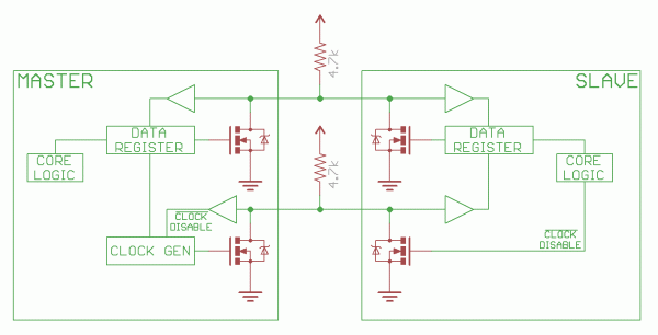
Notice the two pull-up resistors on the two communication lines.
Resistor selection varies with devices on the bus, value of resistor is 4.7k and adjust down if necessary. I2C is a fairly robust protocol, and can be used with short runs of wire (2-3m). For long runs, or systems with lots of devices, smaller resistors(2.2k) are better.
I2C allows for some flexibility in connecting devices with different I/O voltages. In general, in a system where one device is at a higher voltage than another, it may be possible to connect the two devices via I2C without any level shifting circuitry in between them. The trick is to connect the pull-up resistors to the lower of the two voltages. This only works in some cases, where the lower of the two system voltages exceeds the high-level input voltage of the the higher voltage system–for example, a 5V Arduino and a 3.3V accelerometer. There are also I2C level shifters which can be used to connect to two I2C buses with different voltages.
Masters and Slaves
The devices on the I2C bus are either masters or slaves. The master is always the device that drives the SCL clock line. The slaves are the devices that respond to the master. A slave cannot initiate a transfer over the I2C bus, only a master can do that. There can be, and usually are, multiple slaves on the I2C bus, however there is normally only one master. It is possible to have multiple masters, but it is unusual and not covered here. On your robot, the master will be your controller and the slaves will be our modules such as the SRF08 or CMPS03. Slaves will never initiate a transfer. Both master and slave can transfer data over the I2C bus, but that transfer is always controlled by the master.
Protocol in brief
I2C Physical Protocol
I2C Physical Protocol
When the master (your controller) wishes to talk to a slave it begins by issuing a start sequence on the I2C bus. A start sequence is one of two special sequences defined for the I2C bus, the other being the stop sequence. The start sequence and stop sequence are special in that these are the only places where the SDA (data line) is allowed to change while the SCL (clock line) is high. When data is being transferred, SDA must remain stable and not change whilst SCL is high. The start and stop sequences mark the beginning and end of a transaction with the slave device.
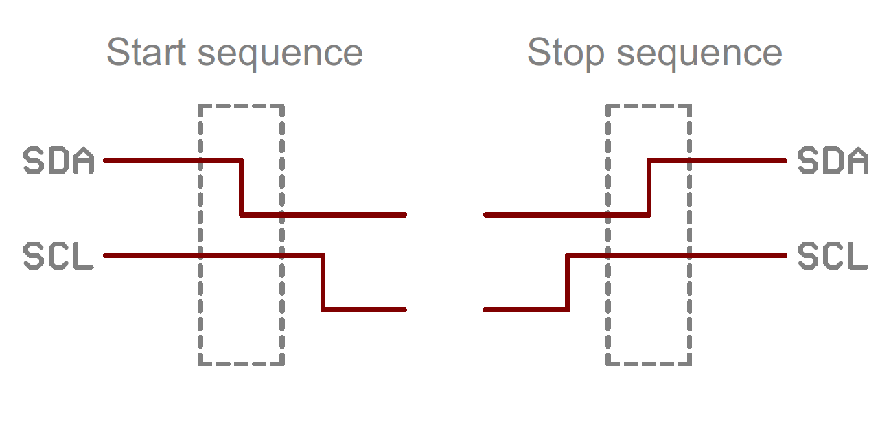 |
| Start and stop sequence |
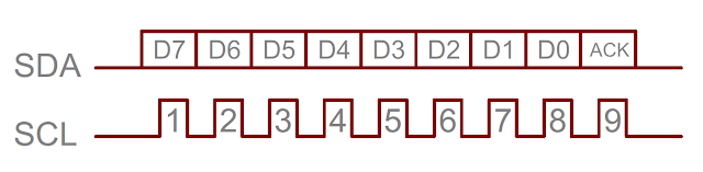
Data is transferred in sequences of 8 bits. The bits are placed on the SDA line starting with the MSB (Most Significant Bit). The SCL line is then pulsed high, then low. Remember that the chip cannot really drive the line high, it simply "lets go" of it and the resistor actually pulls it high. For every 8 bits transferred, the device receiving the data sends back an acknowledge bit, so there are actually 9 SCL clock pulses to transfer each 8 bit byte of data. If the receiving device sends back a low ACK bit, then it has received the data and is ready to accept another byte. If it sends back a high then it is indicating it cannot accept any further data and the master should terminate the transfer by sending a stop sequence.
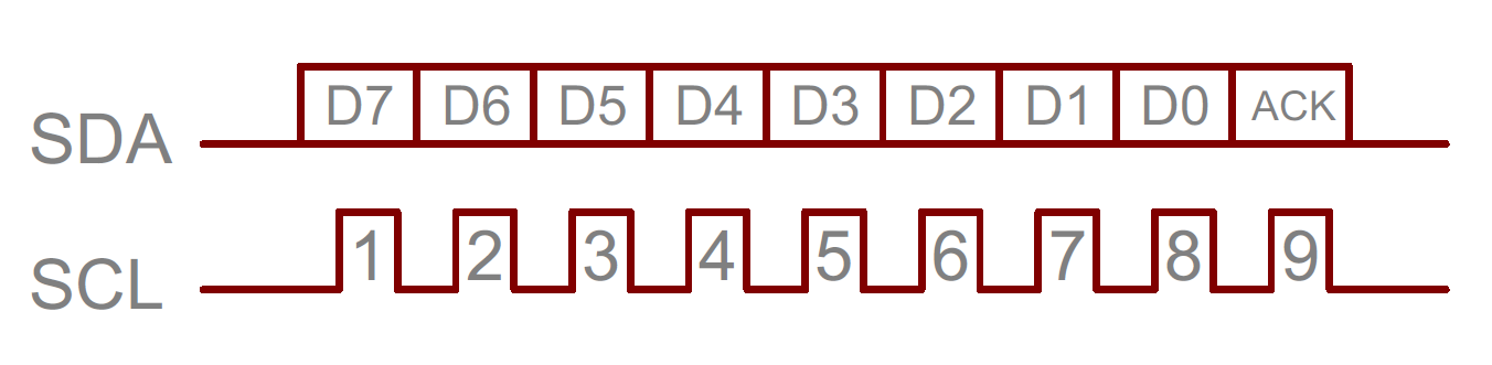
All I2C addresses are either 7 bits or 10 bits. The use of 10 bit addresses is rare and is not covered here. All of our modules and the common chips you will use will have 7 bit addresses. This means that you can have up to 128 devices on the I2C bus, since a 7bit number can be from 0 to 127. When sending out the 7 bit address, we still always send 8 bits. The extra bit is used to inform the slave if the master is writing to it or reading from it. If the bit is zero the master is writing to the slave. If the bit is 1 the master is reading from the slave. The 7 bit address is placed in the upper 7 bits of the byte and the Read/Write (R/W) bit is in the LSB (Least Significant Bit).


Basics


Messages are broken into two types of frame:
- Address frame.
- Data frames.
Address frame, where the master indicates the slave to which the message is being sent, and one or more data frames, which are 8-bit data messages passed from master to slave or vice versa. Data is placed on the SDA line after SCL goes low, and is sampled after the SCL line goes high. The time between clock edge and data read/write is defined by the devices on the bus and will vary from chip to chip.
Start Condition
To initiate the address frame, the master device leaves SCL high and pulls SDA low. This puts all slave devices on notice that a transmission is about to start. If two master devices wish to take ownership of the bus at one time, whichever device pulls SDA low first wins the race and gains control of the bus. It is possible to issue repeated starts, initiating a new communication sequence without relinquishing control of the bus to other masters; we’ll talk about that later.
Address Frame
The address frame is always first in any new communication sequence. For a 7-bit address, the address is clocked out most significant bit (MSB) first, followed by a R/W bit indicating whether this is a read (1) or write (0) operation.
The 9th bit of the frame is the NACK/ACK bit. This is the case for all frames (data or address). Once the first 8 bits of the frame are sent, the receiving device is given control over SDA. If the receiving device does not pull the SDA line low before the 9th clock pulse, it can be inferred that the receiving device either did not receive the data or did not know how to parse the message. In that case, the exchange halts, and it’s up to the master of the system to decide how to proceed.
Data Frames
After the address frame has been sent, data can begin being transmitted. The master will simply continue generating clock pulses at a regular interval, and the data will be placed on SDA by either the master or the slave, depending on whether the R/W bit indicated a read or write operation. The number of data frames is arbitrary, and most slave devices will auto-increment the internal register, meaning that subsequent reads or writes will come from the next register in line.
Stop condition
Once all the data frames have been sent, the master will generate a stop condition. Stop conditions are defined by a 0---->1 (low to high) transition on SDA after a 0---->1(low to high) transition on SCL, with SCL remaining high. During normal data writing operation, the value on SDA should not change when SCL is high, to avoid false stop conditions.
Write to a slave device
- Send a start sequence
- Send the I2C address of the slave with the R/W bit low (even address)
- Send the internal register number you want to write to
- Send the data byte
- [Optionally, send any further data bytes]
- Send the stop sequence.
Reading from the slave
- Send a start sequence
- Send the I2C address of the slave with the R/W bit low (even address)
- Send the internal register number you want to read
- Send a start sequence again (repeated start)
- Send the I2C address of the slave with the R/W bit low (odd address)
- Read data byte from slave
- Send the stop sequence.
nice post, but post any example for program using I2c protocol...
ReplyDeletenice post, but post any example for program using I2c protocol...
ReplyDeleteNice blog… Thanks for sharing very useful information about electrical circuits.
ReplyDeleteElectronic project building for beginners